Appendix C — Radiometric Calibration and Terrain Correction of SAR data
This appendix expands on the radiometric processing chain summarized in Section Data Preprocessing, focusing on the choice of backscatter convention and the role of terrain in radiometric normalization, following the taxonomy of [1].
From digital numbers to calibrated backscatter
SAR backscatter is recorded in phase, used to determine the distance to a target, and amplitude, indicating the amount of signal returning to the sensor. Intensity is calculated from the phase and amplitude and stored as digital numbers (DN). Radiometric calibration converts DN to a physically meaningful backscatter coefficient by normalizing by a reference area to obtain backscatter per unit area. The simplest calibrated quantity is the radar brightness \(\beta^0\), defined as the calibrated intensity divided by the slant-range pixel area \(A_\beta\) (see Figure Figure C.1). Because \(\beta^0\) assumes no Earth model, it is a property of the radar measurement alone and forms the conceptual root from which all other conventions are derived [2].
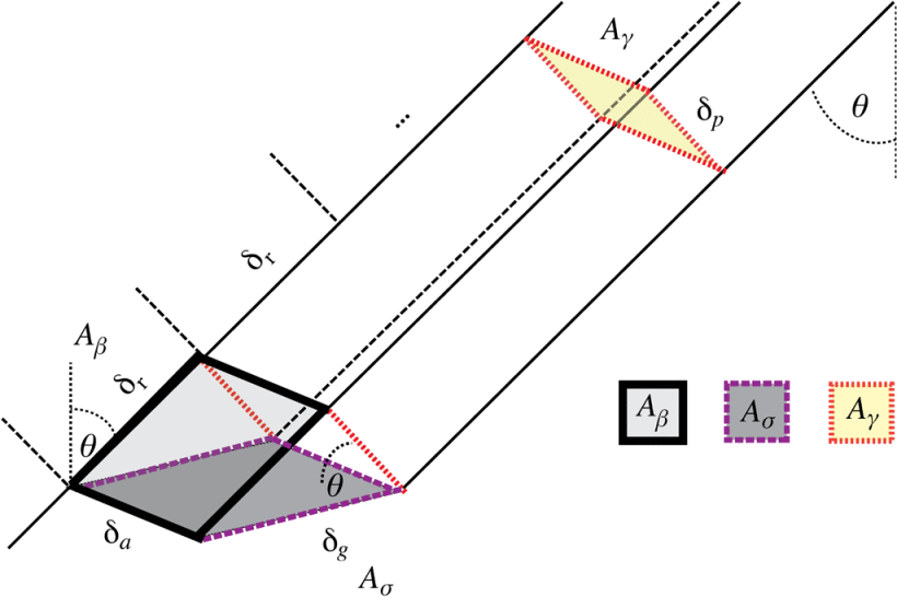
The conventional backscatter coefficient \(\sigma^0_E\) normalizes by the ground-range area \(A_{\sigma}\), giving \(\sigma^0_E = \beta^0 \cdot \sin\theta_E\), where \(\theta_E\) is the incidence angle with respect to the ellipsoid. The \(\gamma^0_E\) convention divides by the area perpendicular to the line of sight \(A_\gamma\), giving \(\gamma^0_E = \beta^0 \cdot \tan\theta_E\). Note that a model of the Earth is required to gain knowledge of the incident angle \(\theta_E\) to calculate \(\sigma^0\) or \(\gamma^0\).
The problem with the ellipsoid assumption
None of \(\beta^0\), \(\sigma^0_E\), or \(\gamma^0_E\) accounts for local relief: the areas they normalize by are derived from the ellipsoid, but the true illuminated area of a pixel depends on the terrain. A slope tilted toward the sensor exposes more surface area than the ellipsoid assumes and therefore appears brighter; a slope tilted away exposes less and appears darker. Pixel intensity becomes partly a function of topography rather than ground properties, biasing any task that compares backscatter across relief: land cover classification, biomass retrieval, change detection, or the mosaicking of ascending and descending passes.
Terrain-referenced conventions
Radiometric terrain correction (RTC) replaces the ellipsoid-derived reference area with one computed from a digital elevation model (DEM). Two terrain-referenced conventions are in common use. The \(\sigma^0_T\) convention applies a per-pixel scalar correction based on the local incidence angle (LIM), \(\sigma^0_T = \sigma^0_E \cdot \sin\theta_{\text{LIM}}/\sin\theta_E\), where \(\theta_{\text{LIM}}\) is derived from the DEM. This correction assumes that a single planar facet contributes to each pixel and only adjusts for its tilt. [1] argues that such angle-based normalizations are flawed due to their failure to account for many important properties of radar backscatter in regions with significant topographic variation. They introduced the \(\gamma^0_T\) convention that instead integrates the illuminated facet areas rigorously over the DEM, accumulating contributions from all terrain facets that map to a given SAR pixel. This handles cases of steep or complex relief where multiple facets contribute per pixel, which a local-angle scalar correction cannot represent. \(\gamma^0_T\) is therefore preferred over \(\sigma^0_T\) whenever significant relief is present, and is the default terrain-flattened output of modern processors, such as ESA SNAP [3].
Relationship to geometric terrain correction
Radiometric terrain correction is distinct from geometric terrain correction (GTC), which uses a DEM and the Range-Doppler algorithm to relocate pixels from radar coordinates to map coordinates. GTC corrects where pixels sit; RTC corrects what their values mean. The two operations share the same geometric mapping between SAR and DEM coordinates and are typically computed together, but they are conceptually independent: an image can be geometrically correct while remaining radiometrically biased on slopes, and backscatter can be terrain-flattened in radar geometry before being geocoded. GTC alone is adequate for visual interpretation over relatively flat terrain; quantitative analysis across significant relief generally requires both corrections, with \(\gamma^0_T\) as the natural input convention for any downstream task that compares backscatter across topographically varied scenes.